For this session, you will have to calibrate a camera and use the calibration data to reconstruct the skeleton of a posing model.
Calibration
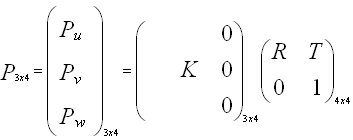
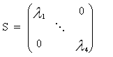
In the pinhole camera model, a camera can be defined by two matrices: the intrinsic matrix and the extrinsic matrix. The intrinsic matrix contains all the properties of the internal structure of the camera: focal length, image format and principal point. The intrinsic matrix is called K, and can be written as follows (f_u and f_v represent the focal length in term of pixels, u_0 and v_0 are the coordinates of the principal point):
The extrinsic matrix is related to the position of the camera in the world. It defines how to go from the world coordinate system to the camera coordinate system. It can be represented as a rotation matrix and a translation matrix.
The process of camera calibration consists in recovering those two matrices. To do that, we will use the Bouguet Camera Calibration Toolbox, which is available here You can follow the first tutorial, and calculate the intrinsic matrix of the camera, K. Use the files im*.jpg that you can find here.
Reconstruction of a posing model

This part tackles the methods that are commonly used in Motion Capture. The goal here is to reconstruct the 3D skeleton of our posing model, from a pair of photos taken from different angles. In real Motion Capture, the model wears markers that are easily trackable by a set of cameras (due to the material they are made of). A 3D reconstruction of all the markers is done for each frame over a period of time, which results in an animated skeleton which can be used on a 3D model to create realistic CG animation.
To make this part more easy, we use the same camera for both shots, to avoid having to calibrate the intrinsics of two different cameras. Note that to be able to use this trick, the model has to be absolutely still between the two shots (in reality, two different cameras should take a photo at exactly the same time). We will pretend from now on that we used two cameras.
The first part of the process is to calculate the extrinsics (ie. rotation and translation) of both cameras. This can be done easily with the toolbox, by using a single photo of the checkerboard (one for each camera, of course the checkerboard should not move). By doing that, the checkerboard will actually define the world coordinate system (ie. one corner of the checkerboard will be the origin, and its sides will be the unit vectors of the basis). For practical reasons, we make the checkerboard visible on the shots of the model (so we can use them to calibrate), but it is possible to use independent shots of the checkerboard beforehand to perform extrinsic calibration (as long as the position of the cameras stay unchanged after that).
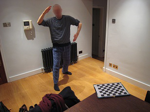
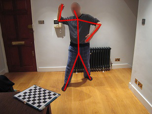
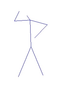
Once the cameras are calibrated, you will have to pick the 2D positions of distinctive parts of the model's body, on both photos. You should pick enough points to build a skeleton, for instance: tip of both foots, inter-leg, collar, elbow, tip of the hands, tip of the nose.

Now let's see the maths behind the reconstruction process. Don't worry, the actual Matlab code that you will have to write to solve the equations fit in 10 lines. We use the following notations:
- We note (Ui*, Vi*) the 2D position measured by the camera.
- We note (Ui, Vi) the projected coordinates of the 3D point on the camera.
- We note n the number of cameras (in our case it will be 2).
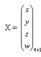
- A 3D point is noted, in homogeneous coordinates:
A 3D point is projected onto the camera by using the projection matrix P, defined as being the product of the intrinsic matrix and the extrinsic matrix:
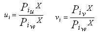
Note that Pu, Pv and Pw are 1x4 vectors. To project a point X onto the camera, we multiply its homogeneous coordinates by P. This gives us another homogeneous vector. We get the 2D position of the point by dividing by the last coordinates w. We can then write:
Now the problem is the following: we want to find the position of the 3D point X, such that, in an ideal world, the measured 2D position and its calculated 2D projection are the same. Because we cannot have an exact solution, we actually want to minimise the error between the measured position and the calculated projection. We define the error, and develop it as follows:
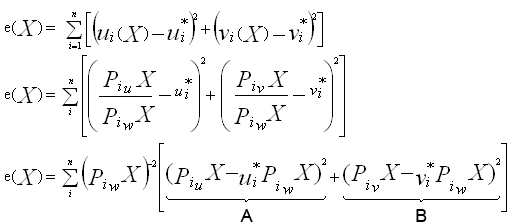
We want to minimise this error. This is equivalent to minimising the right hand side of this equation, which is equivalent to minimising both terms A and B, since they are both positive.
This is finally equivalent to solving the following linear problem:
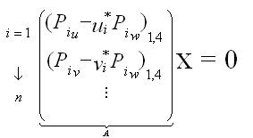
Each camera brings two lines to this matrix, which will be 2n x 4. To have a fully constrained system, we therefore need 2 cameras. This is why we can only reconstruct the 3D position of a point with a minimum of two different views. To solve this system we can use the SVD decomposition of the matrix A:

The position of the 3D point will correspond to the last column of V. Be careful, it is still in homogeneous coordinates. You will have to do this process for each point.
Once you have the position of all the points, you can use the method joinPoints to draw segments between pairs of points in 3D, and build your final skeleton.
Guidelines:
- Calibrate the intrinsic parameters. Save K.
- Calibrate the extrinsics parameters of the two different views. Save R1, T1, R2, T2.
- Pick the points on the model and save them.
- Create projection matrices P1 and P2.
- Solve the linear system for each point
- Display the skeleton in 3D. Display the positions of both cameras and the position of the checkerboard using the code provided.
You can download the different files that you will need here. The squares of the checkerboard are 28mm x 28mm.
Update:
- When calibrating, do not click on the external corners of the checkerboard, instead, click on the corners that are one square before the edges (exactly as they do in the tutorial). This gives you a 7x5 pattern.
- Again the squares are 28mm x 28mm.
- The intrinsics need to be calculated once using the 5 images of the checkerboard. The extrinsics need to be calculated twice (once for each camera), using the photos of the model.
- To build K you have to use the values of the focal length and principal points that the calibration toolbox returns.
- To build the extrinsics matrix, you need the translation vector (T) and the rotation matrix (R) that the calibration toolbox returns, you can forget about the rest.
- If you are using a terminal and/or do not have much memory available, you can use the images that are in the folder small. If you were using the large images and are switching to the small ones, you will have to redo the calibration from the beginning.
- If you are using a Matlab without the image processing toolbox, you can use figure; image(myimage) to display an image. You can use the Data Cursor tool to get the coordinates of the points on the image. If you do have the image processing toolbox, you can use getline to get a list of points, it's more convenient. If nothing is displayed when you run the script, just open an empty figure and run the script again.