The goal of this practical is to combine Direct Manipulation with the ideas in VideoTextures. You will build a system that allows the user to (seemingly) specify the look-at directions of a "real" human face.
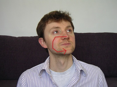
The end-user input to the system is a piecewise linear curve. This curve specifies the linear sections of the path that the video-sprite object should follow. For the default data provided here, the path should specify a sequence of look-at-points of the face.
Your system will follow that user-specified path to traverse a collection of images (could also be video) where the subject was excercising at least two obvious degrees of freedom. The resulting video should be smooth in terms of looking as continuous as possible, and controlled in terms of moving in accordance with the user's directions. In theory, and NOT a required part of this assignment, one could imagine a real-time version of the system, where the human face would turn interactively, in response to click-and-drag mouse inputs.
Grading and Deadline
Uploads of either your final .zip file or that .zip file's MD5 checksum are due by noon on 23rd March. 10% will be deducted for submissions that are less than 24 hours late, 20% will be deducted for submitting between 24 and 48 hrs late, and there is NO credit for solutions submitted more than 48hrs past the deadline.
The Basic Section of the assignment is worth a total of 70%. Each item in the Advanced Section is worth a maximum of 15%. The maximum total grade for this lab is 100%.
Given
You are provided with a 70Mb .zip file containing a collection of photographs. The zip is available online here or locally from ~brostow/prism/gjbLookAtTargets.zip.
As part of this lab, you will need to compute pixel-wise optical flow, and shortest-paths in a graph. For these and any other purposes, you are free to use the optical flow library here for a matlab version (read the instructions, mex it with a recent version of Matlab, and if you are using Linux on the labs, replace in the file "ImageProcessing.h" the functions __max and __min by fmax and fmin, in order to make it compile), or if you don't manage to have that working, you can use this one, but it's slower and works only in graylevel, or finally this one for a binary version that uses CUDA (but it won't work on the Linux labs)You can also use any code offered in the Isomap dimensionality reduction system, especially the different Dijkstra implementations (online here http://waldron.stanford.edu/~isomap/, or locally, with minor changes for compatibility with newer Matlab versions, here and at ~brostow/prism/Isomap.zip). Note: Isomap's Readme.txt explains how to use its dimensionality reduction and Dijkstra routines, which is nice, but Isomap itself is NOT NEEDED for this lab. Document any other code you use that is from someone else - you are being evaluated on the code you contribute yourself. You will be asked to submit the standard CS Department coursework cover sheet.
Output
In the YOUR_NAME_Lab8.zip that you upload, there should be:
- a Readme.txt file explaining how to run your code on a folder containing a collection of images, and what to do to specify the intended multi-stage path for a coordinate in one of the images. For example:
- run labs8('mypath/to/images/'),
- type a number in the specified range to choose your starting image
- left-click on a series of locations in the image to mark the path
- right-click to end drawing
- Output images are saved as <./some_file_####.png>
- Optional: change parameters
to adjust - either in that Readme.txt, or in a separate .html file, briefly explain any Advanced Section items you implemented, and any interesting steps, if any, that you took when implementing the Basic Section.
- a path-comparison image (rasterized or Matlab .fig): a simple image with both the user's desired path, and the actual estimated path of the clicked point, as it tried to mimick each segment of the user's path.
- a video or image sequence of the human face following that path. The path should have at least four segments (so a polyline with 5+ points). The output resolution should be in the range 400x300 or 800x600.
Basic Section (70%)
Submit the items listed in the "Output" section above to show that you've implemented the following algorithm-outline. You are expected to fill in gaps yourself. You can improve on the algorithm if you like, but then you should submit a separate .m file or explain in the Readme.txt how to run both the regular and your improved versions. The following algorithm outline explains ONLY what should happen when your system is trying to find frames from the image collection to traverse one straight line path between the clicked-point s (for source) and t (for target). Obviously, you will need to repeat the process for the other segments of the path
- Compute a Distance Matrix that encodes the similarity in appearance between all the frames in the collection. This matrix can be dense or sparse.
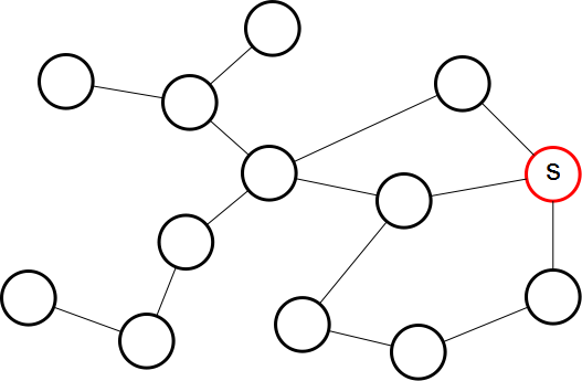
- Convert the Distance Matrix into a graph, where nodes represent images, and edges connect pairs of images whose appearance-distance is small. That distance is the edge-weight. The graph should be one connected component, but not fully-connected. Here is an example:
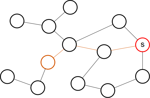
- For each node in the graph, compute the shortest path to the image I where point s was defined. Reverse these paths to get your sequences of nodes, named "Paths", that allow unique traversal from the starting node I (with s) to every other node in the graph (J, K, ...). The following is an example of the shortest path from a node to the source:
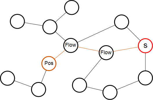
- Compute the advected location of point s in every other node, using optical flow. s in the starting node I "flows" by (0,0) to itself, but by (u,v)_q for each of its Q neighbors in the graph. If one entry in Paths travels from I over 2 edges to reach its final image K (so I->J->K), for example, you'll need to compute the location s' as the flow I->J at s, then compute s'' as the flow J->K at J's point s'. An illustration of that process follows (Pos is calculated using the position s and the flow information).
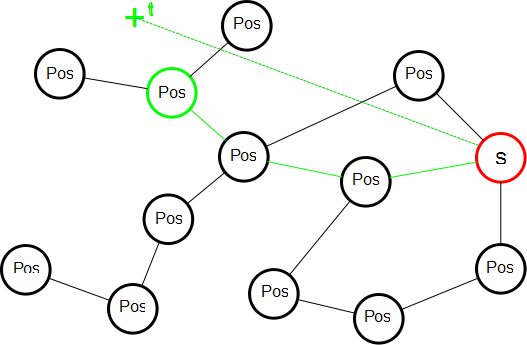
- Pick the path in Paths whose advected location comes closest to the point t (see illustration below). Render this path as the output image sequence for this user-drawn segment.
Advanced Section (15% each)
Items in the Advanced Secion will be evaluated based on effort, creativity, and thoroughness, so don't assume "easy" ones are less work, when they are meant to be roughly equal in difficulty.
- Compute better paths that somehow take both image-difference AND trajectory-similiarity into account.
- Produce and use your own data. You may acquire data with a partner, and you may share your data with others, but SPECIFY SO YOU GET THE RIGHT AMOUNT OF CREDIT. If three people collect the data and share it with five others, the first three each get 1/3 of the points, and the other five get zero (but gain new test-data that will likely be better than the default).
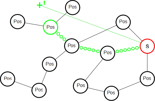
- Render slow motion and multi-node interpolations based initially on the flow between real images in the collection. If synthesized images have artifacts, also consider inventing some post-processing tricks. Slow motion is illustrated in the following graph, where the small green circles have been synthetized:
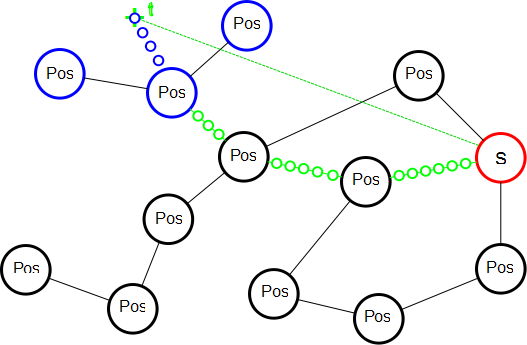
And multi-node interpolation is illustrated in the next one, where the small blue circles are synthetized from the existing large blue nodes, in order to generate a final image where the moving point ends up exactly where the user clicked:
- Synchronize your video to music. Audacity is a good sound-editing program that is free to download.